Zowimanoids
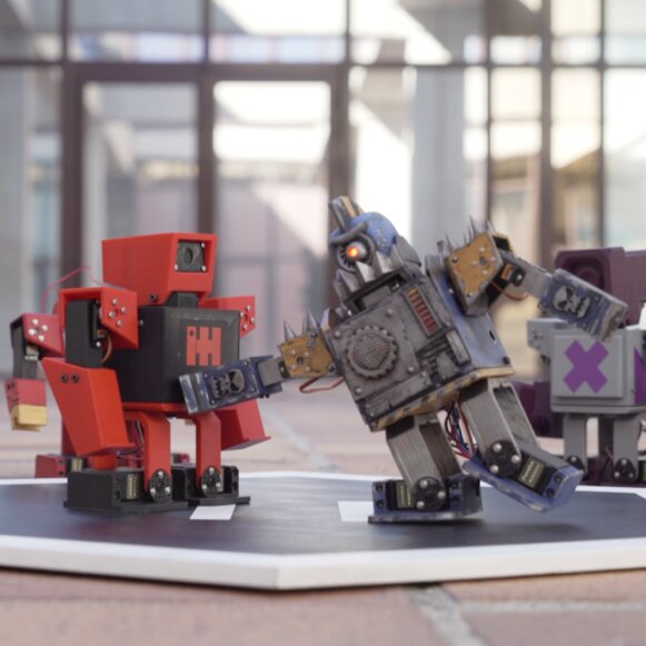
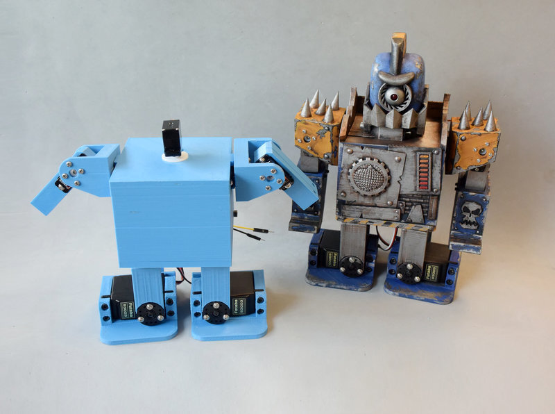
Zowimanoids are modified versions of Zowi with two arms and a head. Because of their shape we called them “micro humanoids”, and they are a good starting point to learn how to handle the movement of many servos at the same time. We published them in February 2016 on DIWO, BQ’s DIY platform, and this is the assembly guide we wrote back then.
Zowimanoids were made by Alberto Arribas, David Sánchez, Sonia Verdú and me, together with the rest of bqlabs, with photos and video by Diego Aldea and María de Prado. They are released under a CC-BY-SA license, and all the sources are in the Zowi repository.
Step 0: the materials
To build a zowimanoid you need the printed parts, the electronics, some screws and nuts and a few tools.
Step 1: the feet
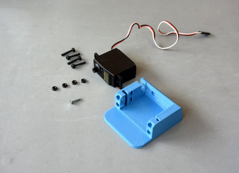
Let’s start with the feet. For the two feet you need:
- 2x printed foot
- 2x standard size servo
- 8x M3x18 screws
- 8x M3 nuts
- 2x M3x12 countersunk screw
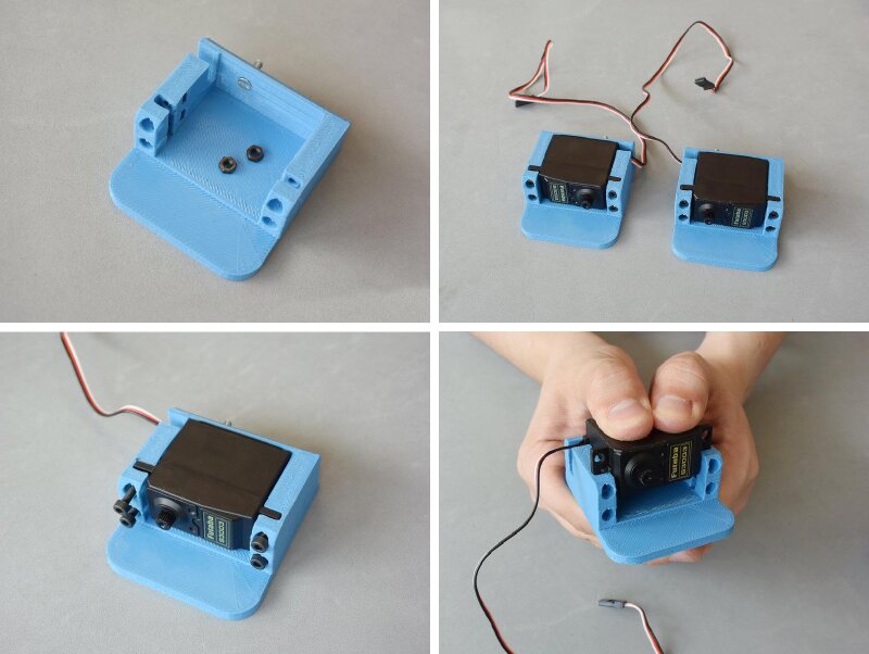
First, put the nuts in the slots of the servo housing and the countersunk screw in the rear hole. Make sure the nuts don’t fall out during the assembly, because once the servo is in place there’s no way to put them back. Then push the servo in with your fingers and screw it in place with the rest of the screws.
Step 2: the legs
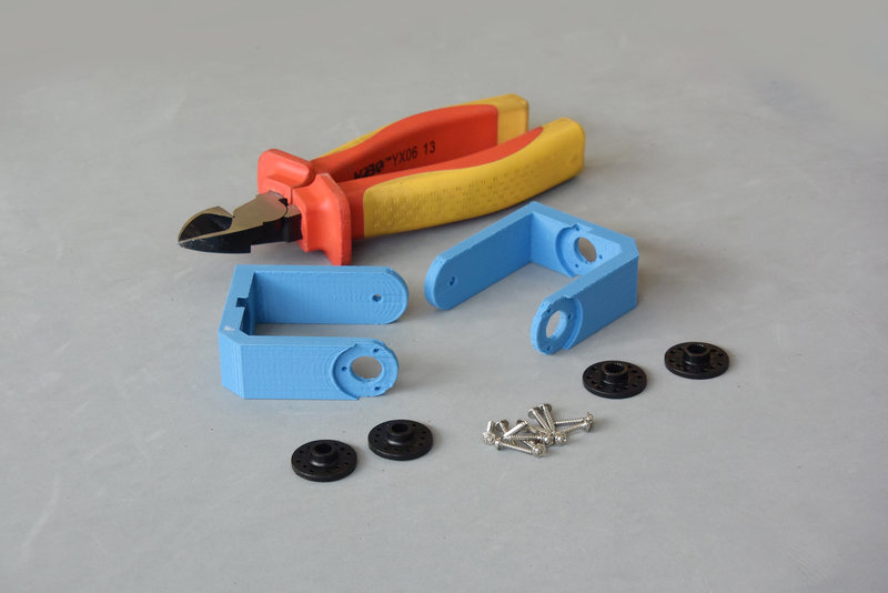
For this step you need:
- 2x printed leg
- 2x standard servo horn
- Servo screws
It’s better to use round horns like the ones in the picture, but if your servos don’t come with them, other horns can be adapted. The screws are the ones that come with the servo. You’ll also need pliers or some other tool to cut the screws.
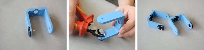
Each horn is fixed with three screws that go through the horn and the leg. Then the screws have to be cut so they don’t rub against the servo case. They are very thin, so a big pair of pliers cuts them easily.
Step 3: the chassis
Now the base of the robot, the chassis. You need:
- 2x standard size servo
- 2x M3 nuts
- 4x short cable ties
The cable ties can be replaced by eight M3x18 screws and eight M3 nuts, but the assembly is a bit more tedious.
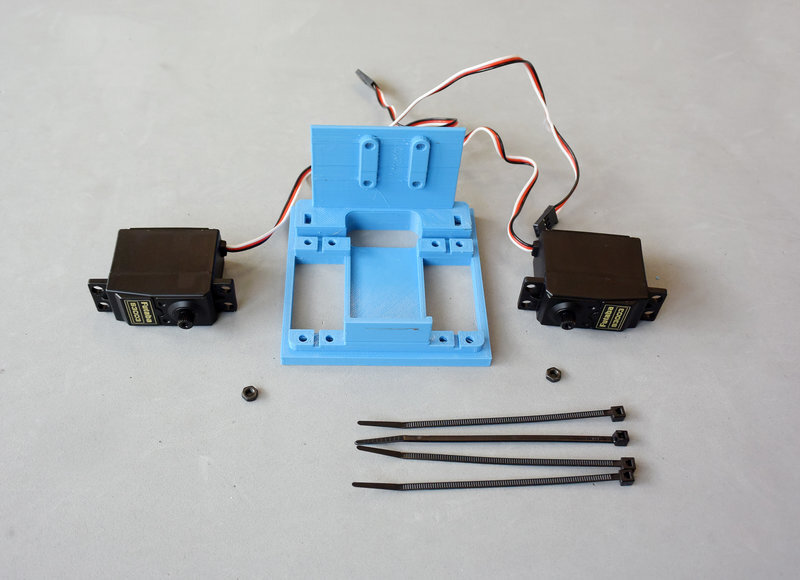
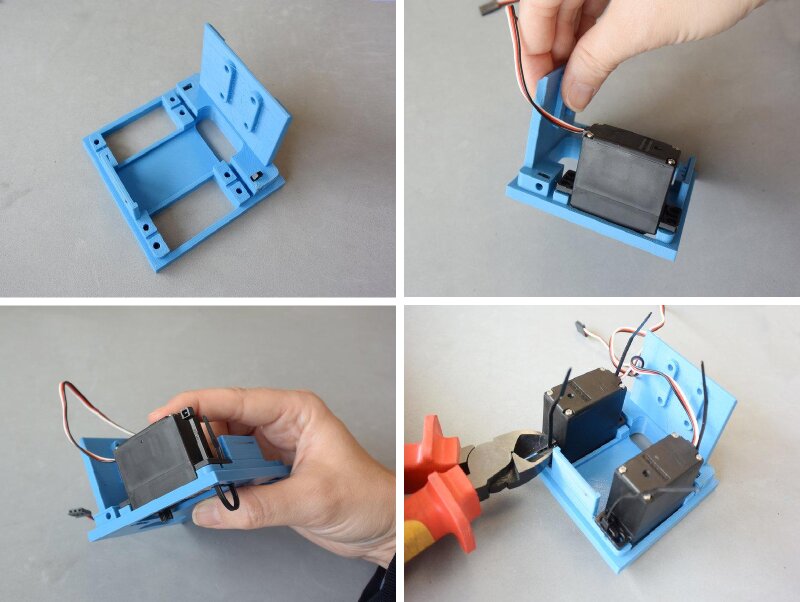
First of all, put the two nuts in the slots of the chassis. They won’t be needed until almost the end, but it’s important to put them in now and not lose them. Using cable ties is much easier than using screws, and the servos end up quite firmly fixed. One detail: the head of each cable tie must stay on the top side of the chassis, otherwise it will rub against the legs.
Step 4: legs to chassis
Now the legs are joined to the chassis. You need:
- The assembly from step 2
- The assembly from step 3
- 2x servo horn screws
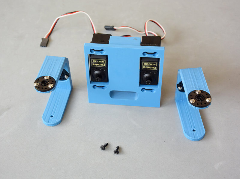
The most critical part of this step is placing the legs so they can move along a range like the one in the pictures. If you turn the leg and the servo by hand and the joint can’t make that movement, take it apart and put it back in a different position. When both legs are right, screw the horns with the servo screws.
Step 5: feet to legs
For this step you need:
- The assembly from step 4
- The assembly from step 1
- 2x servo horn screws
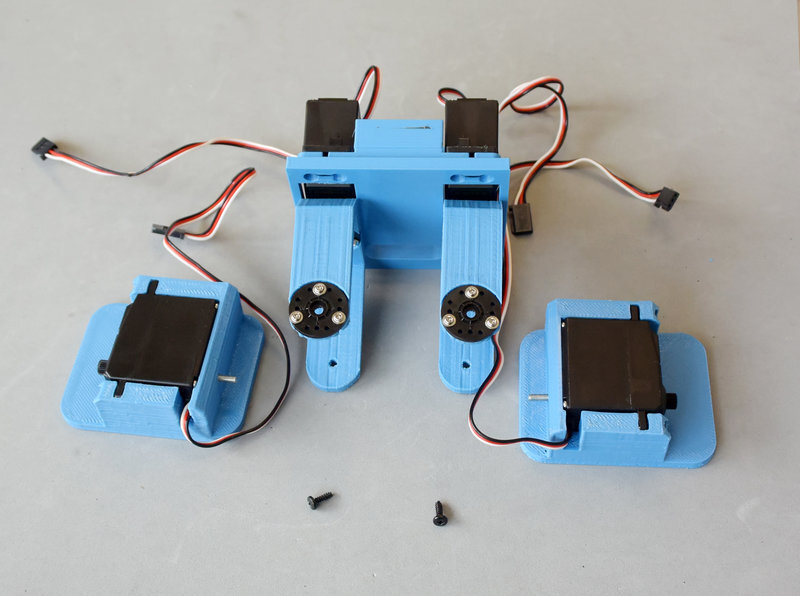
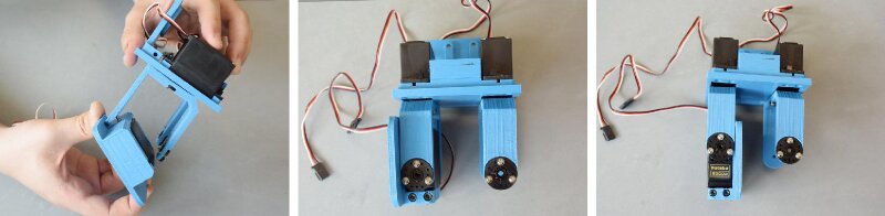
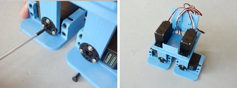
To fit the feet in the legs, start by putting the end of the screw that sticks out of the foot into the hole at the back of the leg. You’ll have to pull the two sides of the leg apart a little, carefully, so it doesn’t break. As in the previous step, the pictures show the range the servo must be able to cover, and again, reposition it as many times as needed. Finally, screw the horns with their screws.
Step 6: the shoulders
With the lower half of the robot finished, let’s go with the shoulders. You need:
- 2x printed shoulder
- 4x micro servo horn
- 16x micro servo screws
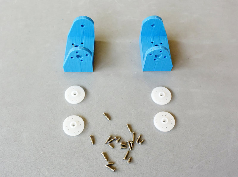
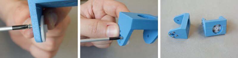
The screws that come with micro servos can be really tiny and fragile, so pick a screwdriver of the right size and be patient. The screws go through the plastic part and bite into the horns. If the hole of the horn is too small, it can be widened with a 2 mm drill or a pointy file. If your servos don’t come with many screws, it’s better to fix each horn with only two and save some for the next steps.
Step 7: the torso
The torso needs:
- 1x printed torso
- 2x micro servo
- 4x micro servo mounting screws
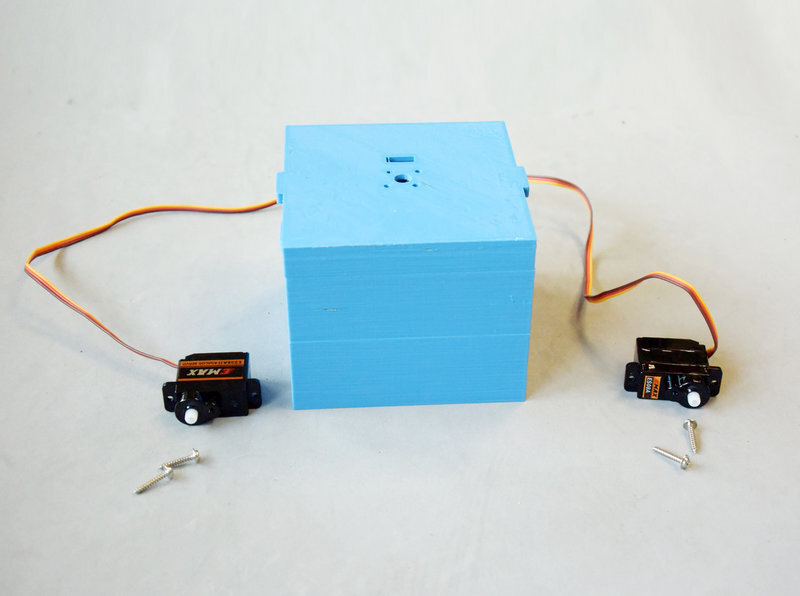
The shaft of each servo must stay between the two tabs of the body. Screw them in that position with the screws that come with the servo (the same ones as in step 6).
Next, the head servo. You need:
- 1x micro servo
- 1x micro servo horn
- 2x micro servo screws
- 1x micro servo horn screw
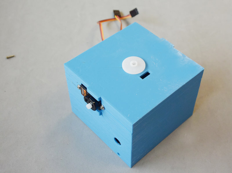
To place it properly, the centre of the servo’s range must end up in the position you can see in these pictures.
Step 8: shoulders to body
Let’s keep going with the torso. You need:
- The assembly from step 6
- The assembly from step 7
- 2x micro servo horn screws
As with the rest of the servos, place them so they can reach the positions shown in the pictures, and then screw them with the screws that come with the servo.
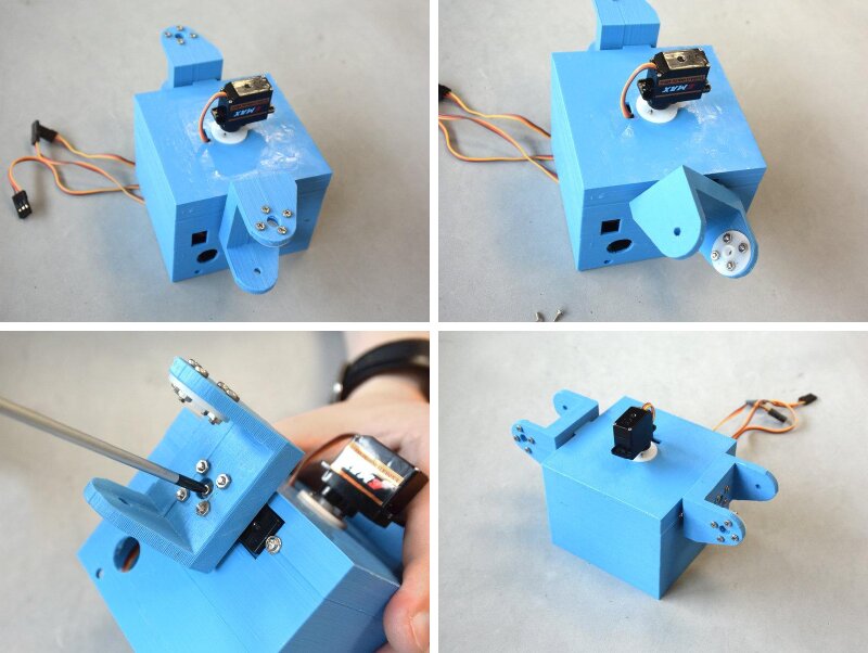
Step 9: the arms
For the arms you need:
- 2x printed arm
- 2x micro servo
- 4x micro servo screws
- 2x M3 nuts
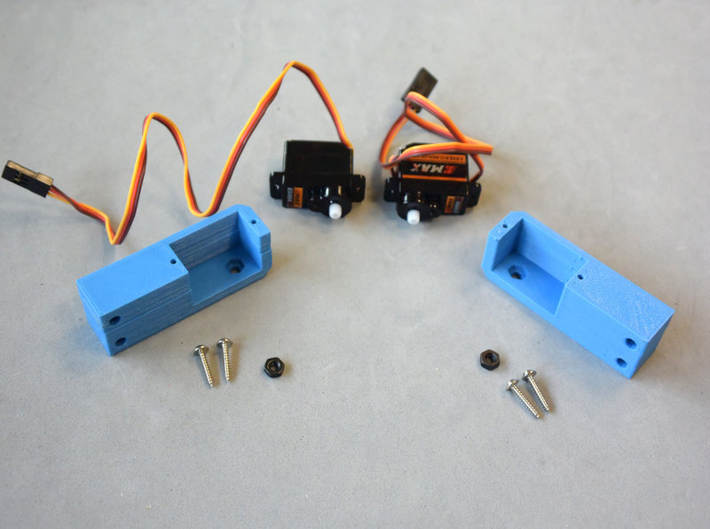
The arms are quite easy. First put the nuts in the hexagonal holes of the printed parts, then put the servo in. Be careful not to pinch the servo cable against the walls of the part. Once in place, fix each servo with two screws.
Step 10: arms to body
Once the arms are done, they are mounted on the shoulders. You need:
- The assembly from step 8
- The assembly from step 9
- 2x M3x10 screws
- 2x micro servo horn screws
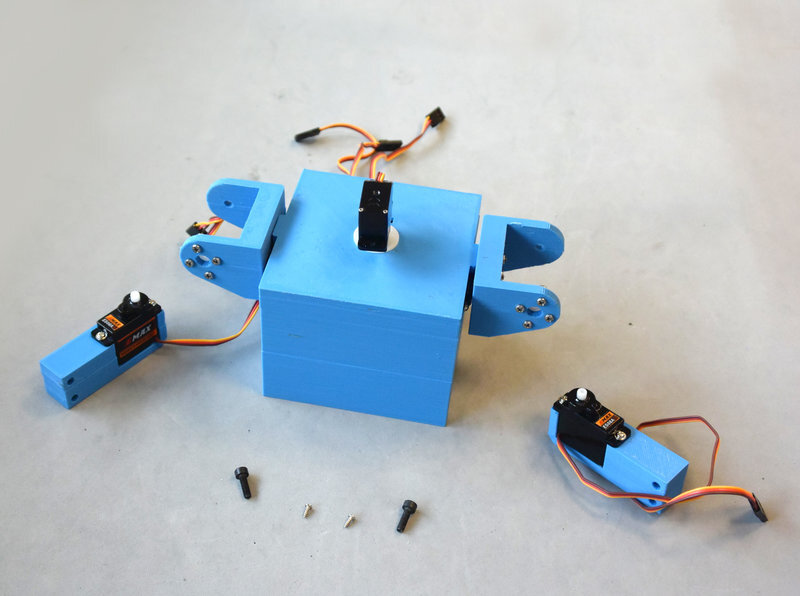
This is very similar to mounting the feet in step 5. Again, check that the arm can move along its whole range, and once it does, fix the horn to the micro servo with its screw. Then put the M3 screw in the rear hole of the shoulder, threading it into the nut inside the arm. Don’t tighten it too much, or it could press against the micro servo case and damage it.
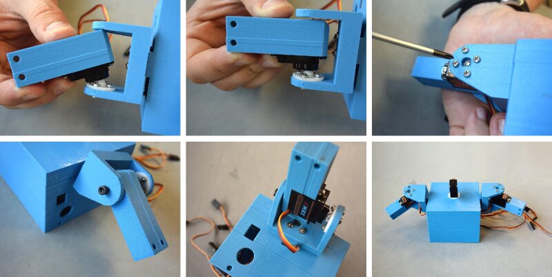
Step 11: electronics
Now the electronics. Here we use a BQ ZUM Core board, which drives the servos, powers them and has Bluetooth. You need:
- The assembly from step 5
- 1x BQ ZUM Core
- 2x M3x12 screws
- 2x M3 nuts
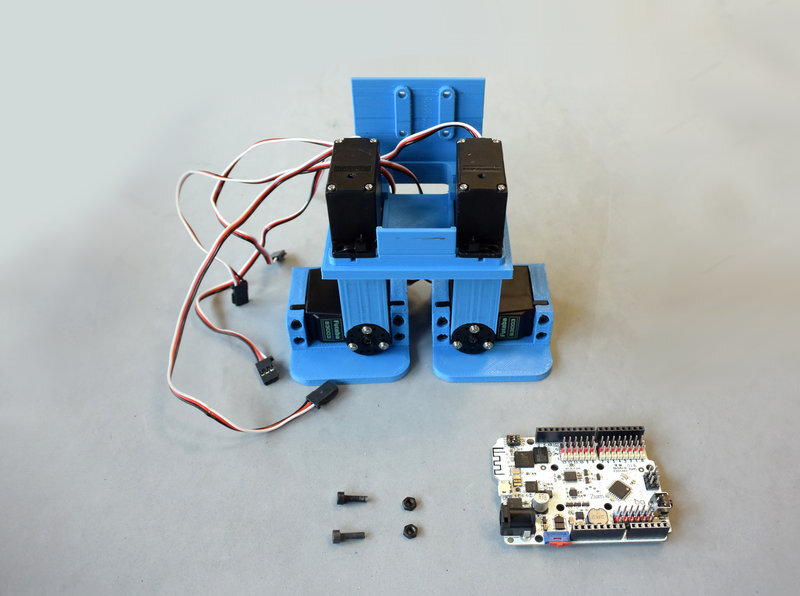
The board goes on the back of the chassis. There are four holes, but two screws hold it firmly enough. Be careful not to damage the components of the board when tightening the screws.
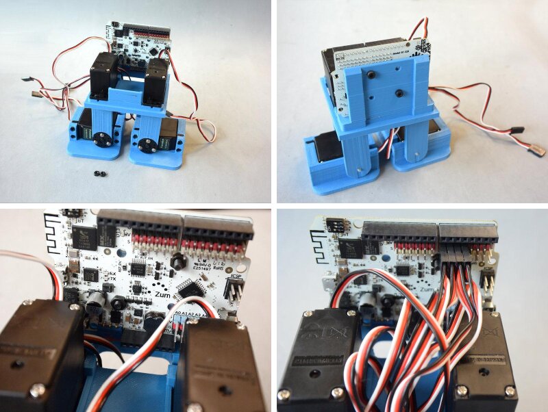
The servos can be connected to any pin between 2 and 12. It doesn’t matter which ones, but write down where each one goes, because you’ll need it to program the robot.
Step 12: battery
There are many options to power the robot. Here we use a two-cell LiPo battery (7.4 V), but a battery holder, a phone power bank or a rechargeable NiMH battery would also work. The most important thing is to respect the input voltage of the board: the ZUM Core accepts between 6 V and 17 V, and it can power the servos through its built-in regulator. With other boards, make sure the servos get enough current, which usually means powering them separately. With an Arduino, for example, the easiest way is to power both the board and the servos directly from a 6 V battery (four alkaline batteries, five rechargeable ones or an RC NiMH pack). Another option is using HV servos, which can be connected directly to a two-cell LiPo.
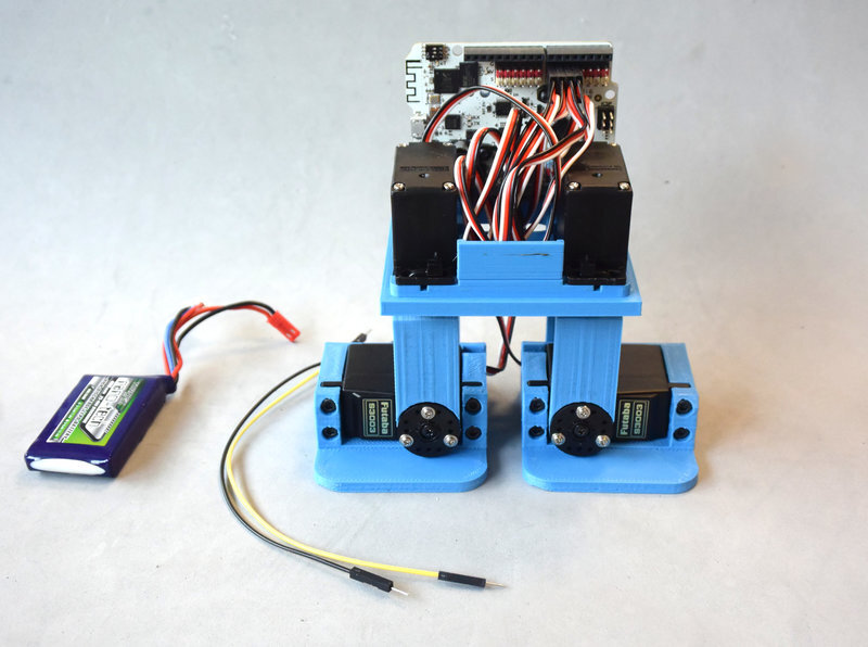
To connect the battery, plug two wires into the Vin and GND pins. Both these wires and the battery connector go out through the hole in the chassis, so the battery can be plugged and unplugged from the outside.
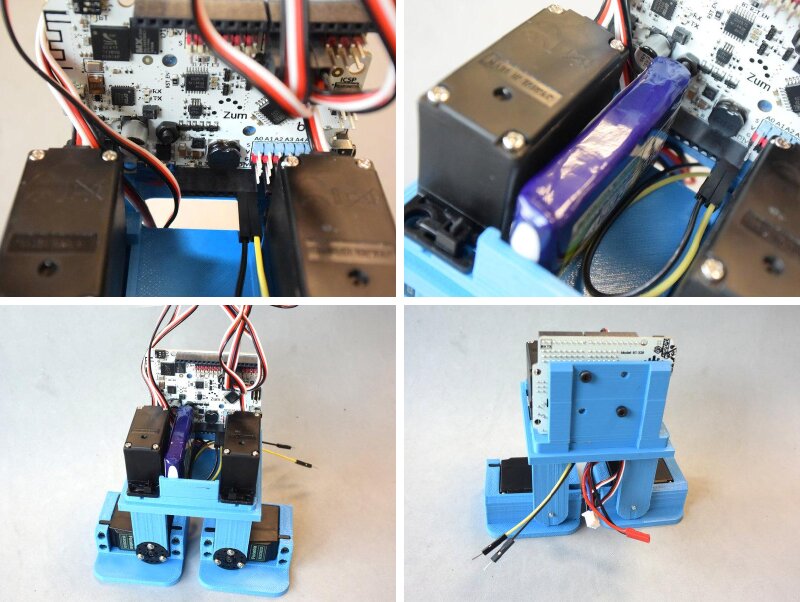
Warning: LiPo batteries need special care, both when charging and when using them. They need a charger able to balance the cells, and misusing them can damage the robot or even hurt you. Always follow the charging instructions of the battery, and the storage recommendations too.
Step 13: closing the body
Last step! To finish the assembly you need:
- The assembly from step 10
- The assembly from step 12
- 2x M3x10 screws
As with the leg servos, plug the arm servos into any of the free pins between 2 and 12, and remember to write down where each one goes, since you’ll need it in the code. Put the body on the chassis and fix it with the two M3 screws.
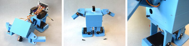
If you’ve made it this far, your zowimanoid is assembled! It still has no hands and no head, though. You have two options: use one of the open designs in the Zowi repository, or (highly recommended) design your own with the FreeCAD template.


Comments