
Micropanda
Micropanda is a microsumo robot I built in 2019: two robots inside a ring, and the first one to push the other out wins. In microsumo the robot must fit in a 5x5 cm square and weigh 100 g at most. Like Ratatron and Pandatron, it’s based on an STM32F103.
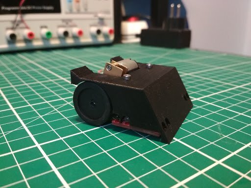
It meets both limits, and there’s still some weight left to add ballast.
Design
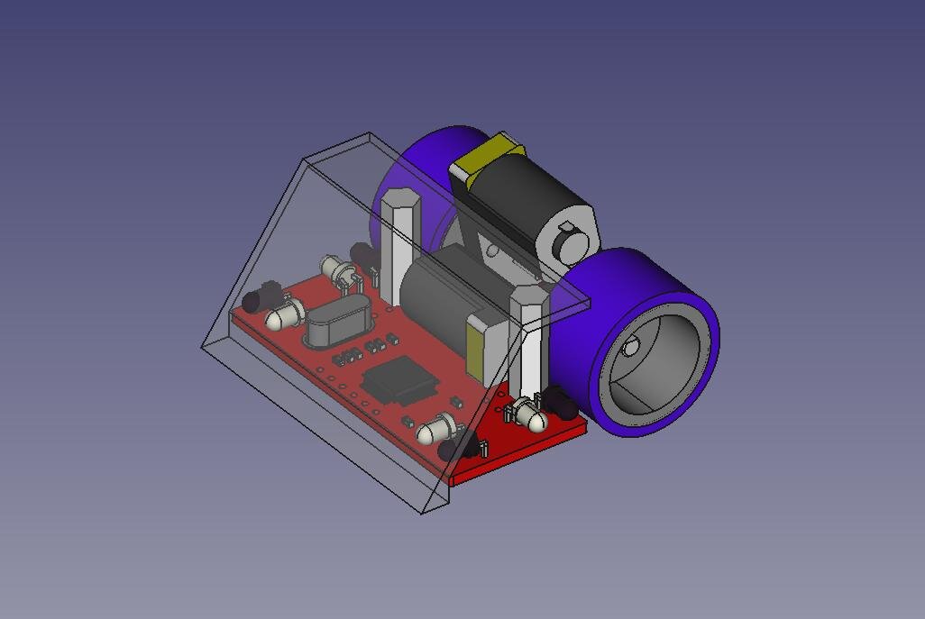
I started in FreeCAD, placing the board, the motors and the wedge-shaped body to check that everything fit in 5x5 cm.
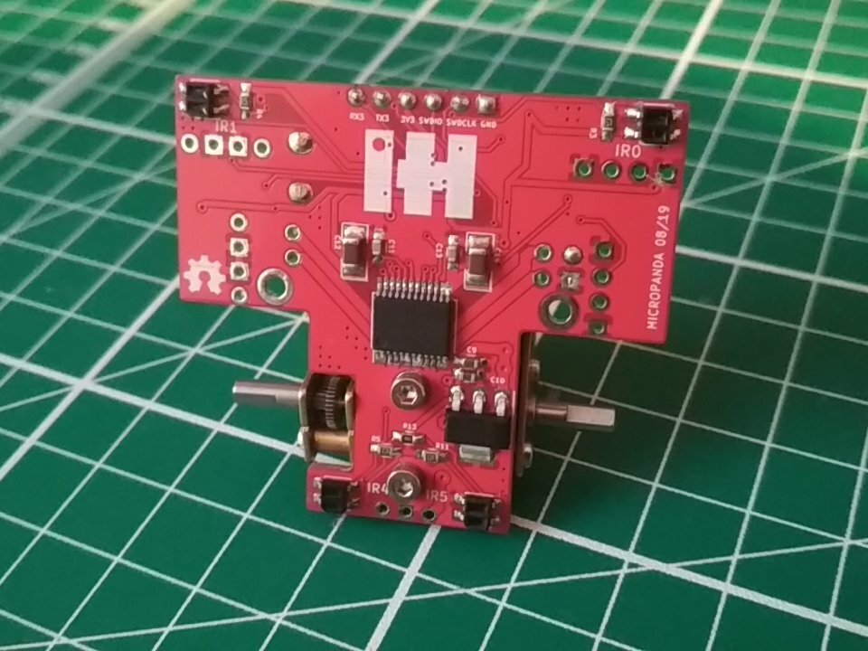
Then the PCB in KiCad. It’s T-shaped: the motors sit on the stem of the T and the sensors go on the wide part.
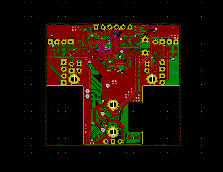
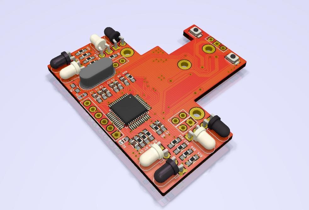
Besides the STM32F103C8T6, the board has a TB6612FNG motor driver and an MCP1824 regulator for the 3.3 V. It runs on a 1S LiPo, and a small step-up module raises the voltage to 12 V for the motors. They’re N20 motors, so 12 V overdrives them, and I got around 500 rpm at the wheels.
Seeing the opponent
The usual choice to find the opponent is a Sharp sensor, but Sharps are big for a 5x5 cm robot. Instead, Micropanda uses four pairs of discrete IR LEDs and phototransistors, two looking forward and two looking to the sides.
The circuit is as simple as it gets:
- Emitter: each IR LED is driven straight from an STM32 pin through a 100 Ω resistor, with no transistor. This way the firmware can switch each one on and off whenever it wants.
- Receiver: each phototransistor has a 5 kΩ pull-up to 3.3 V and its collector goes to an ADC input. The more IR light comes back, the more current flows and the lower the voltage gets.
The problem is that the light in the venue (and the sun) also has IR, so a single reading can’t tell my LED’s light from the rest. The fix is to take two readings. The firmware runs a small scheduler from the SysTick, every 100 µs:
- Read the four phototransistors with the LEDs off. That’s the ambient light.
- Turn the LEDs on and wait 1 ms.
- Read again and turn the LEDs off.
- Subtract both readings. What’s left is only the light from my LEDs that bounced off something.
This cycle repeats every 2 ms. The ADC scans the eight channels non-stop with DMA, so each reading is just taking the last value from a buffer. With these values, the strategy is simple: if both front sensors see the opponent, full speed ahead; if only one sees it, turn towards that side.
It has a trade-off: the detection distance depends on how much light the opponent reflects (a matte black robot is much harder to see than a shiny one), while a Sharp measures by triangulation and the colour matters much less. In exchange, the pairs are tiny, light and cheap, and I can point them wherever I want.
To detect the white edge of the ring there are four QRE1113 sensors underneath. Inside they’re the same idea, an IR LED and a phototransistor in a single package, but these LEDs are always on.
Assembly
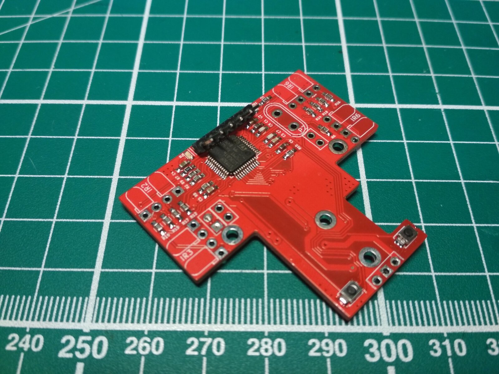
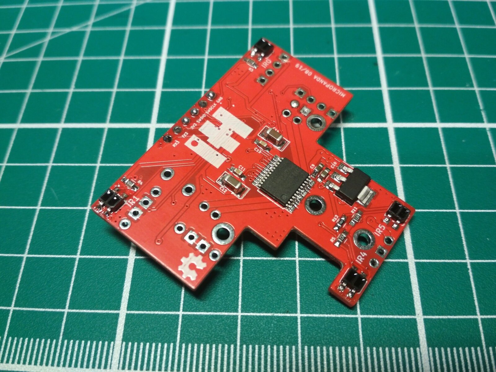
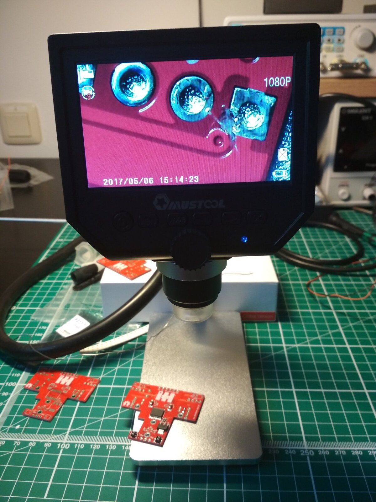
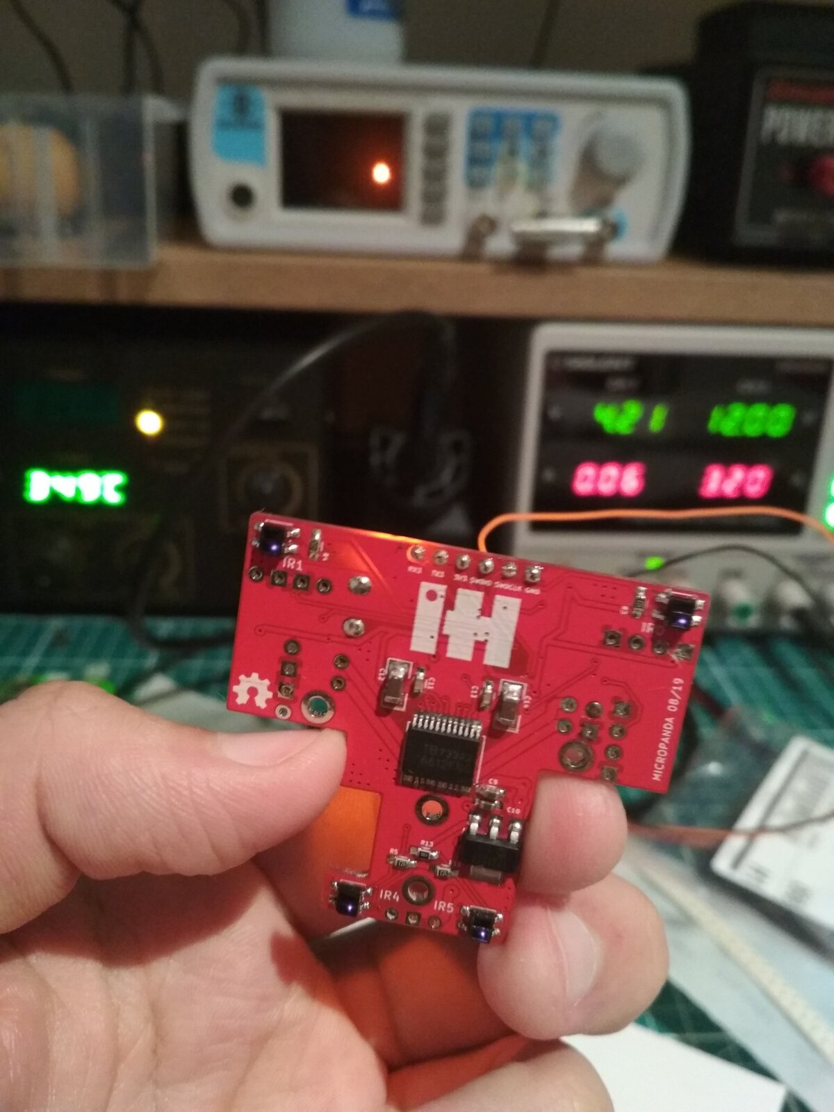
When I powered up the first board, something was off. I checked it under the microscope and found a via touching a pad: a routing mistake in KiCad. Once that was fixed, the board came to life.
The motors go on a 3D printed support screwed to the stem of the T.
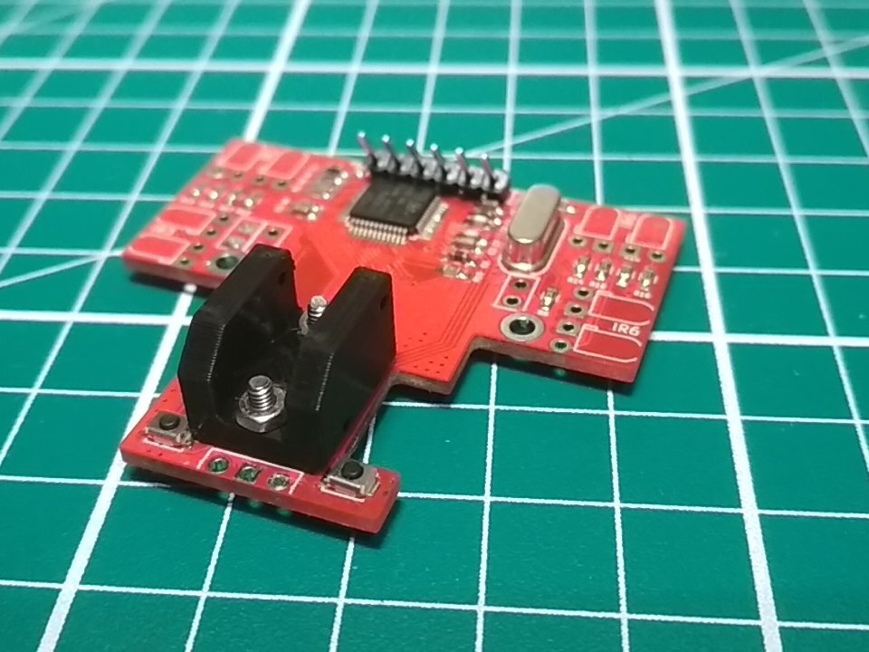
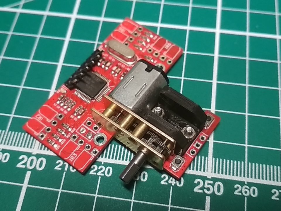
Both motors in place, still without wheels:
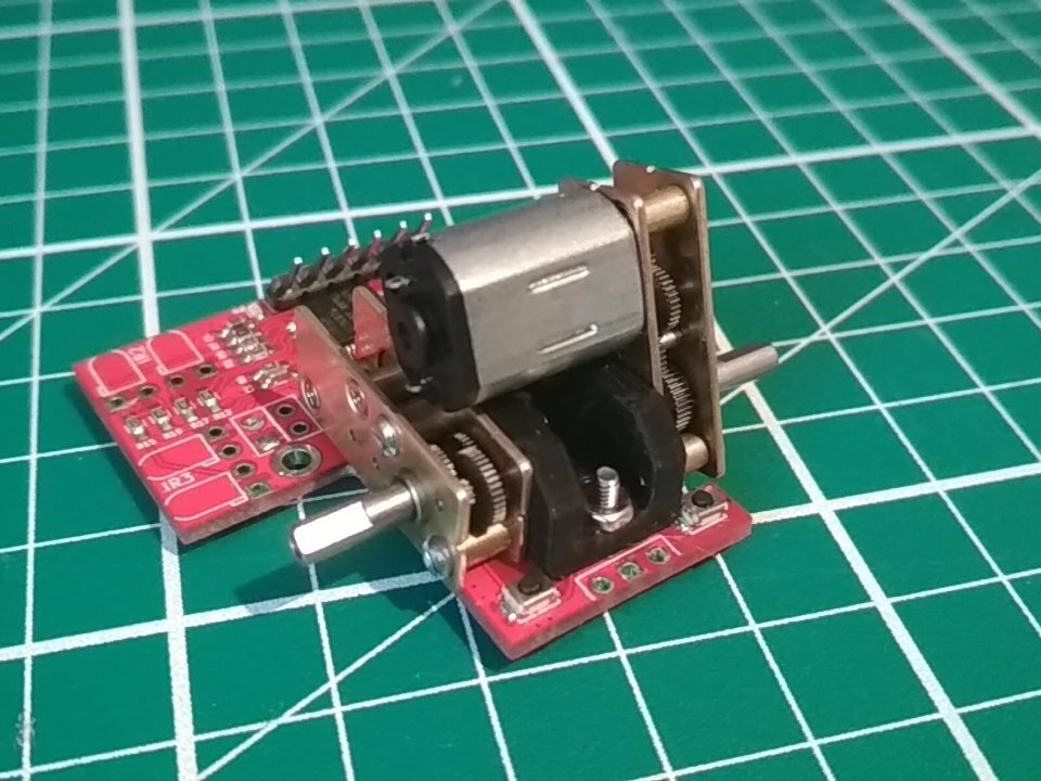
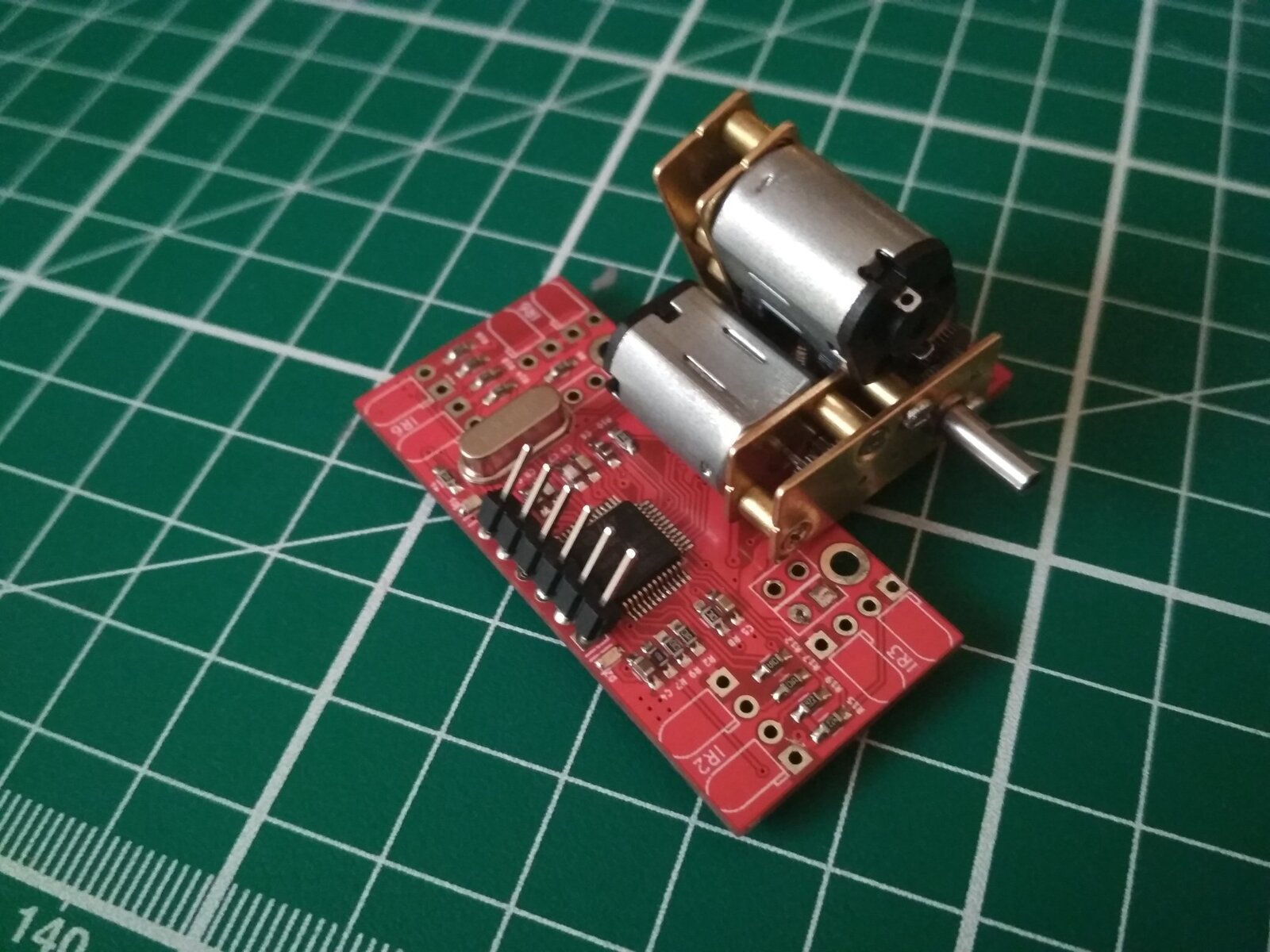
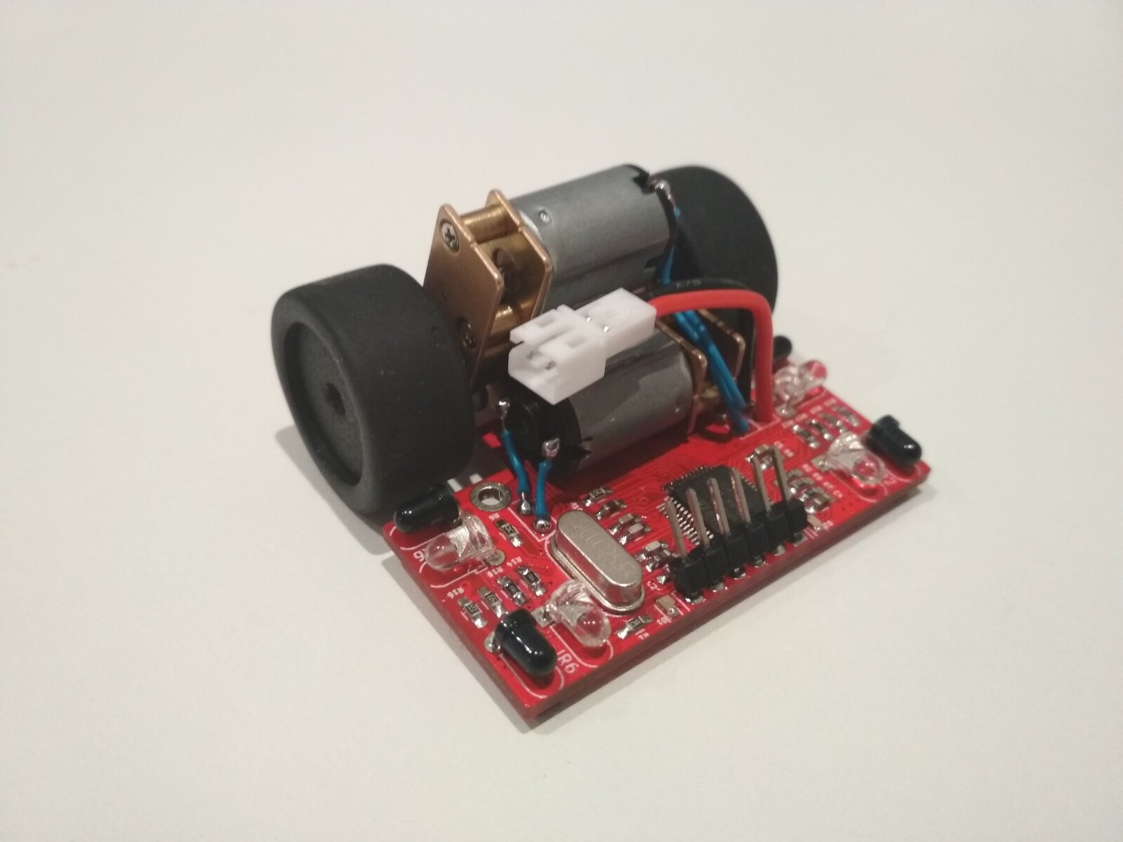
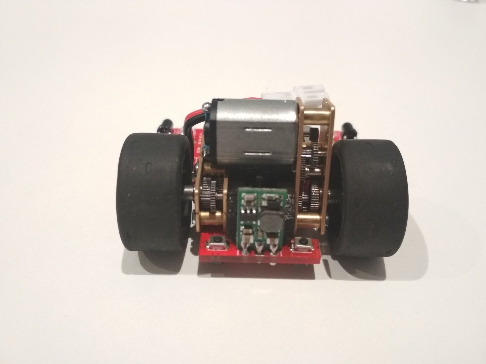
And this is how it looks with everything in place, before putting the body on:
Testing
Here it is detecting a roll of tape and attacking it:
It never took part in an official competition: there’s no microsumo category at OSHWDem (yet!), so it only had some friendly matches against other visitors’ robots at the event.
As always, everything is open source, you can find the firmware, PCB files and printable parts on my GitHub repo.
License
Hardware: CC-BY-SA
Software: GPLv3


Comments