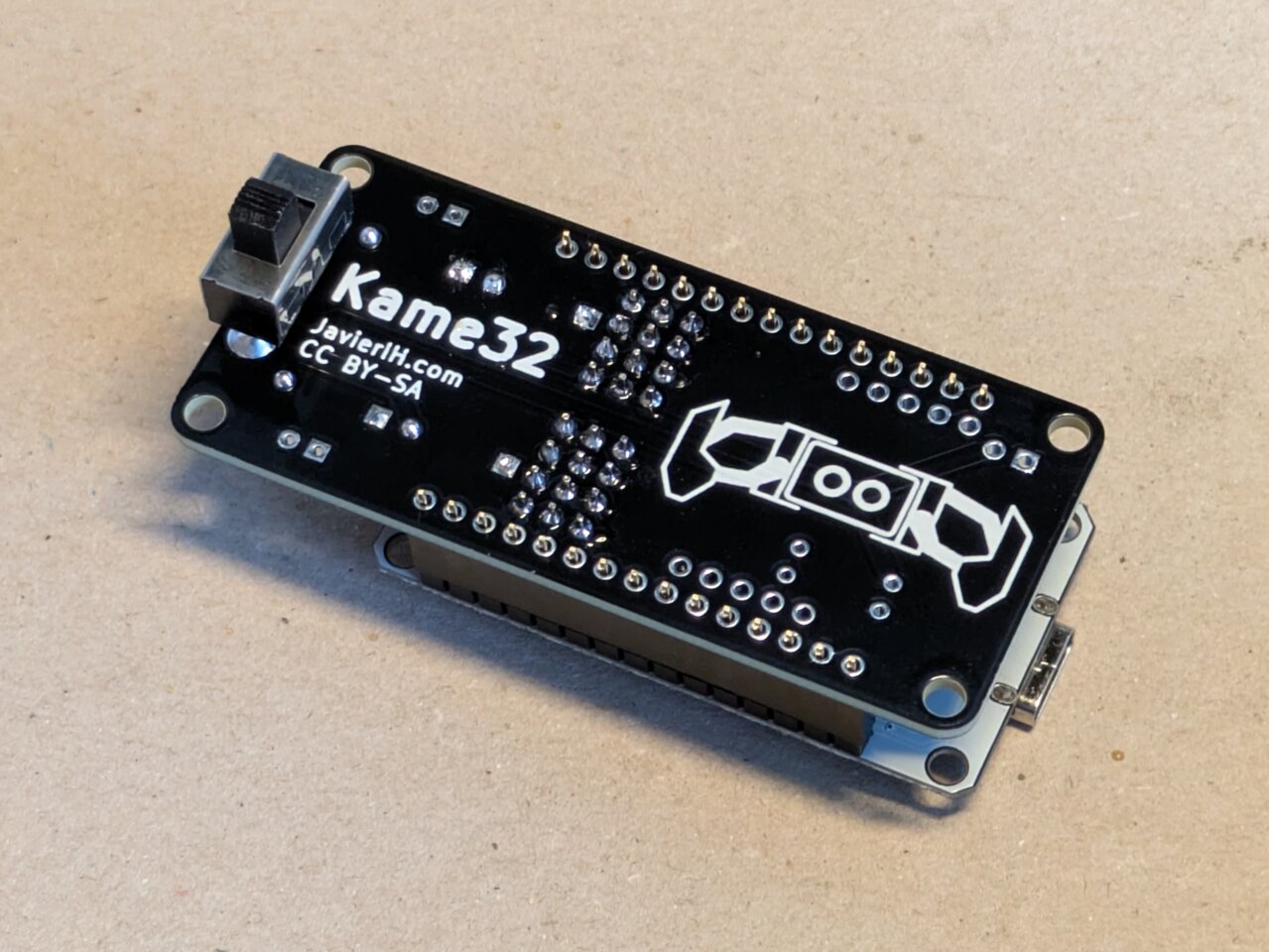
Kame32 PCB
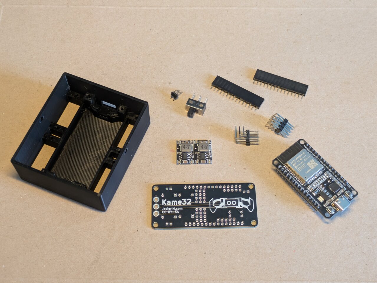
This PCB was designed to make it easy to connect all the servos of the Kame32 robot to the ESP32. If you’d like to get one, you can order it through PCBWay and support the project. Alternatively, you can download the gerber files directly from GitHub. The needed components are listed in the Kame32 BOM
Below you’ll find a step-by-step guide to assemble the board (Sorry for the photo quality, documentation time usually happens late at night when the lighting isn’t great.)
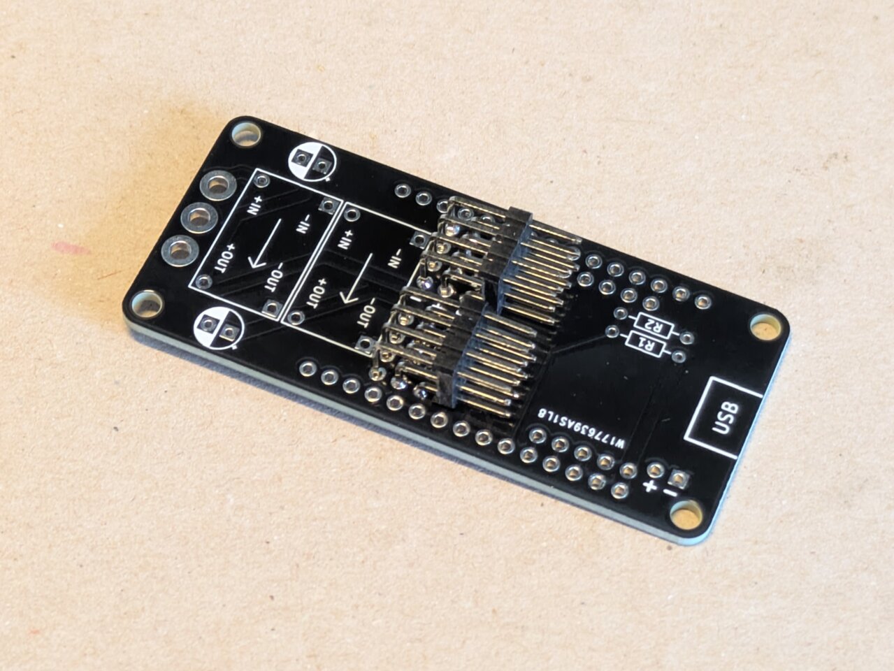
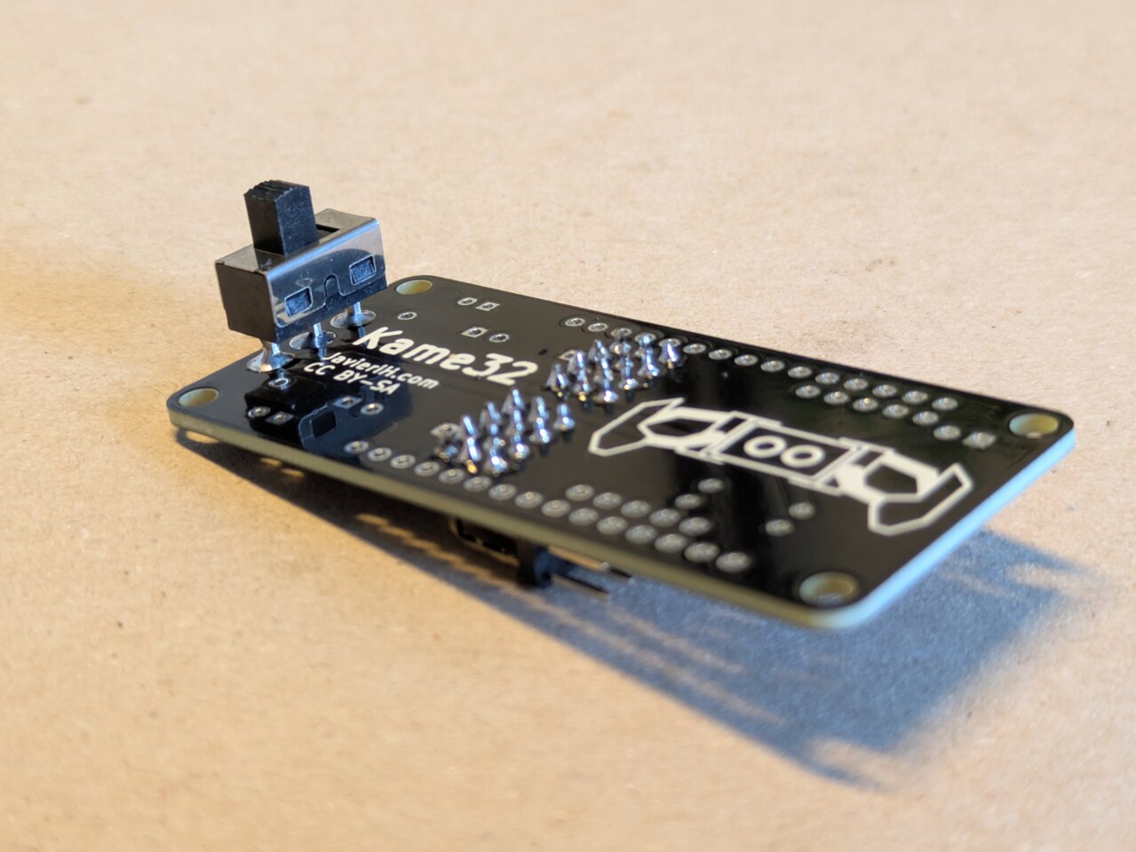
Start by soldering the two triple rows of angled male headers. Tip: Temporarily use the female headers to help align the pins while soldering.
 |
 |
 |
 |
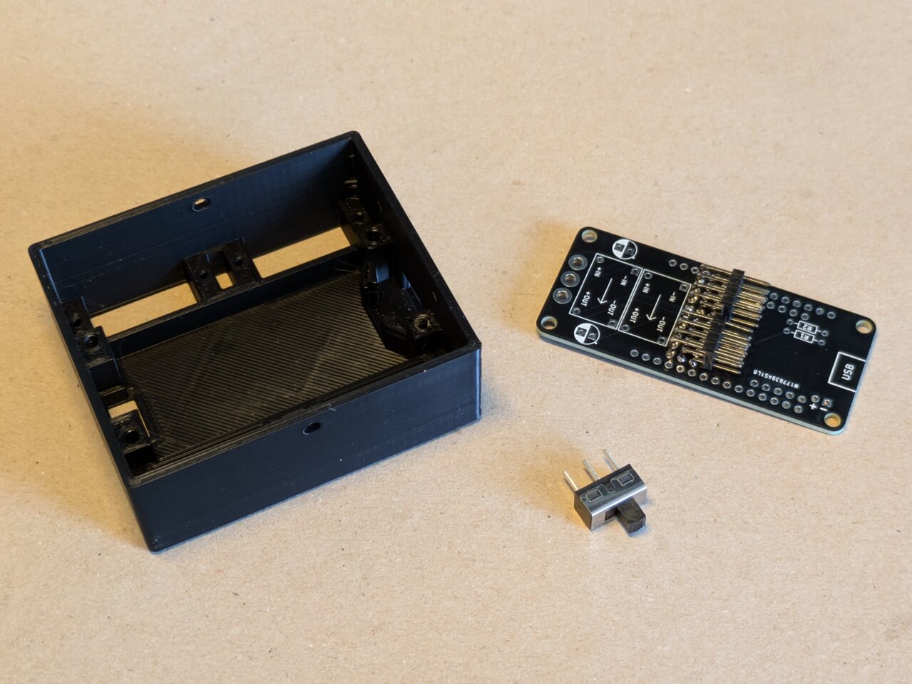
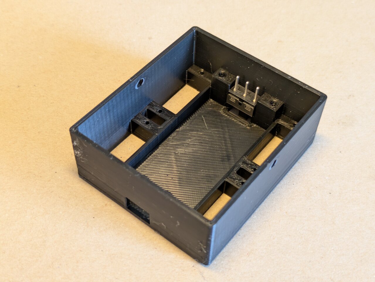
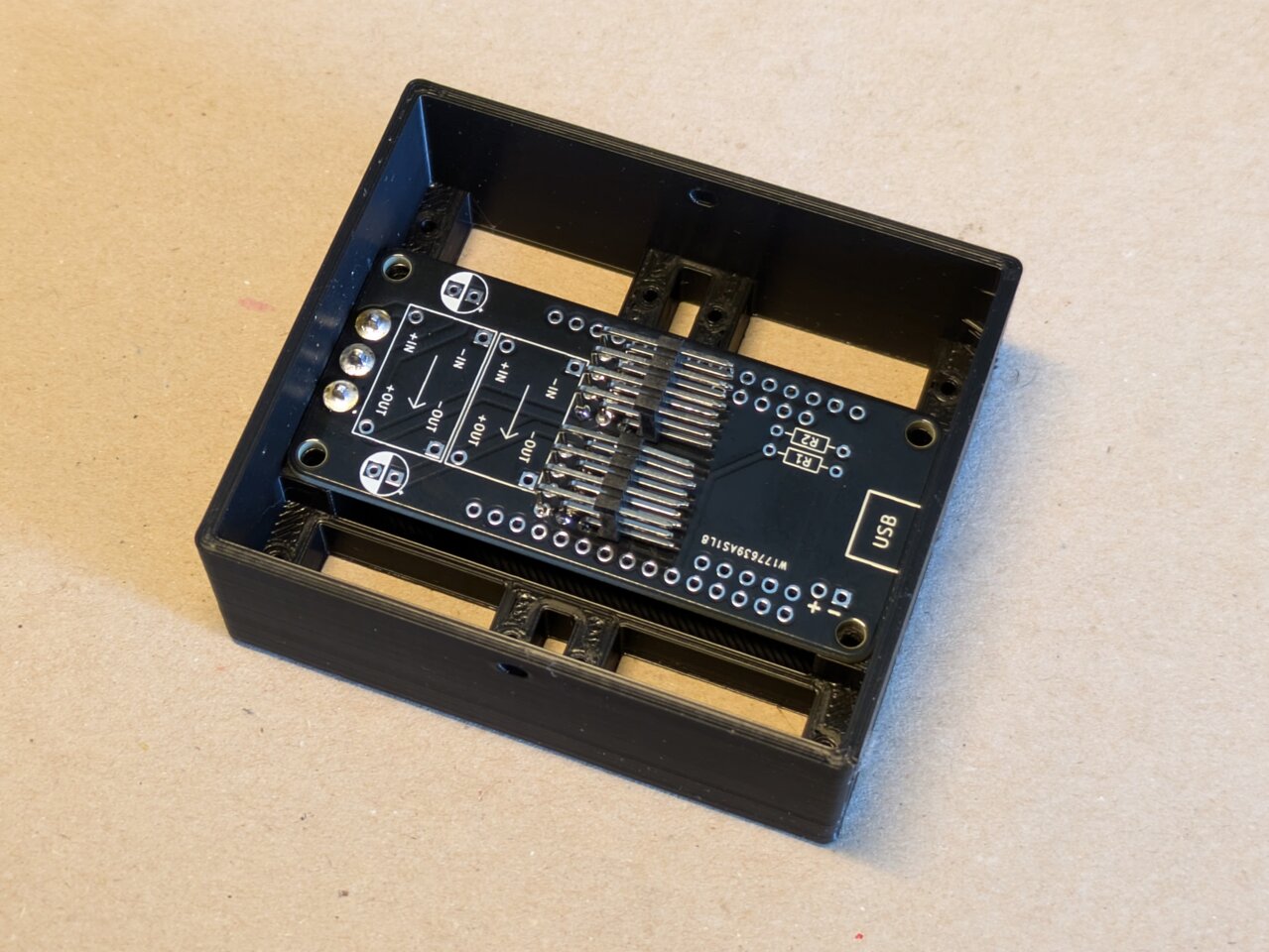
Now solder the power switch. The easiest way is to first place the switch into its slot in the robot’s body. That way, it stays in position and is aligned at the right height when soldered.
 |
 |
 |
 |
 |
 |
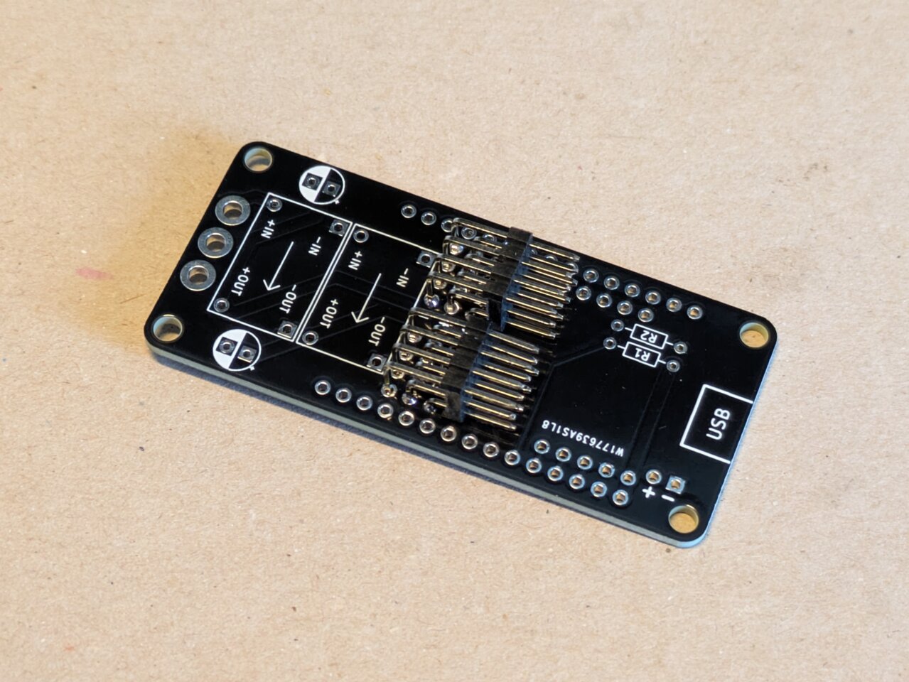
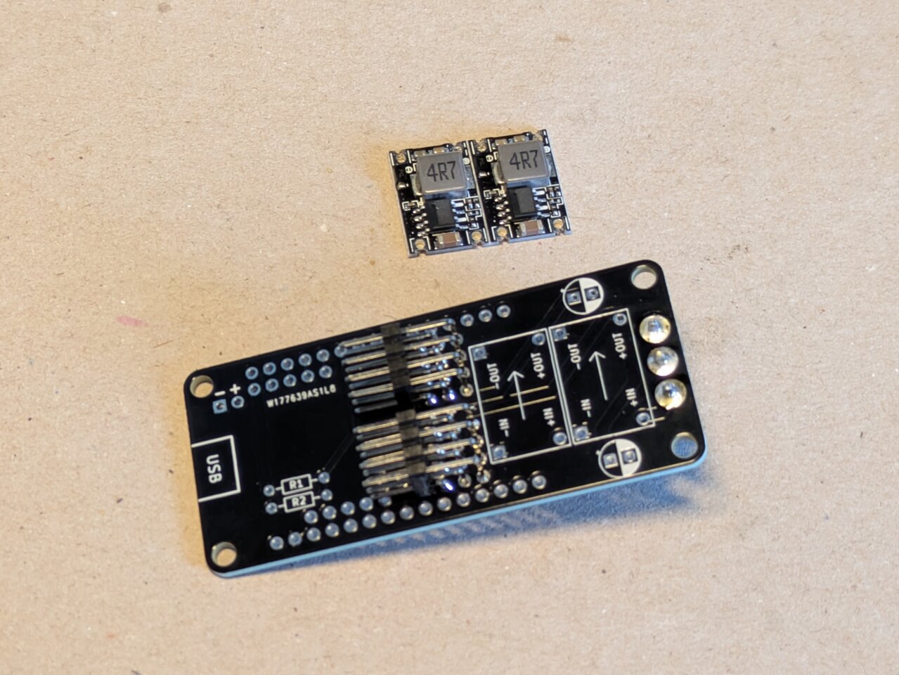
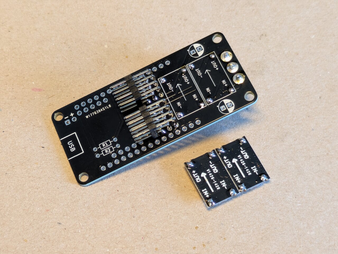
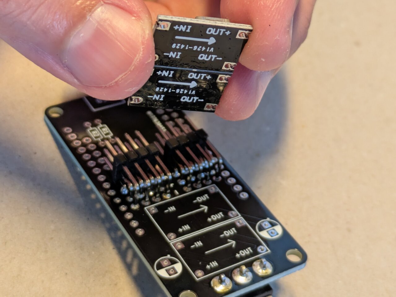
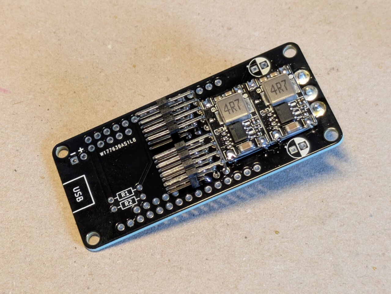
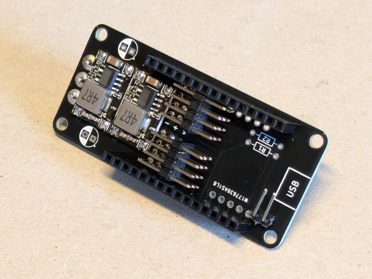
Time to solder the two DC-DC converters. The board in the photos is a previous version with tighter tolerances, so everything is a bit cramped. Don’t worry, if you get your board from PCBWay or use the latest gerbers, those issues are fixed and assembly is easier. I soldered them directly to the PCB, but you can also use pins if you prefer (though it will take up more space).
 |
 |
 |
 |
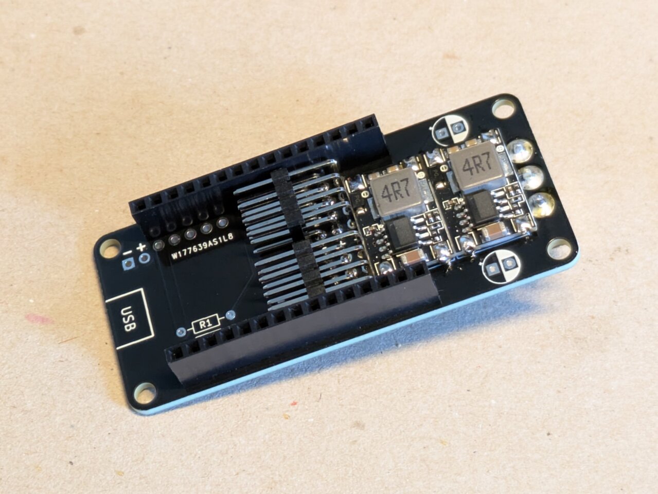
Add the female headers. If you mount them while plugged into the ESP32, it’ll help keep everything aligned while soldering.
 |
 |
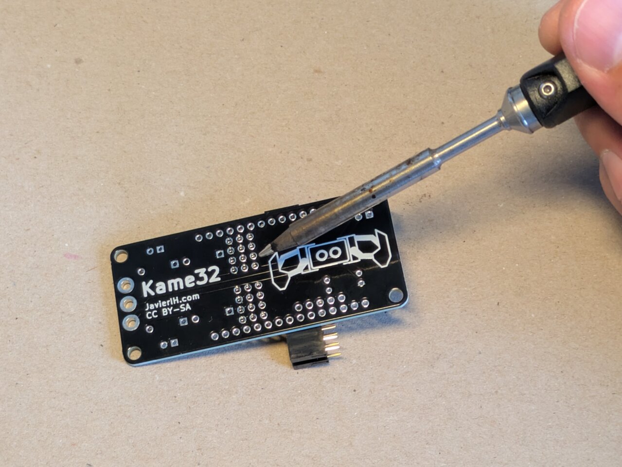
Finally, solder the two angled male pins for the battery connector.
 |
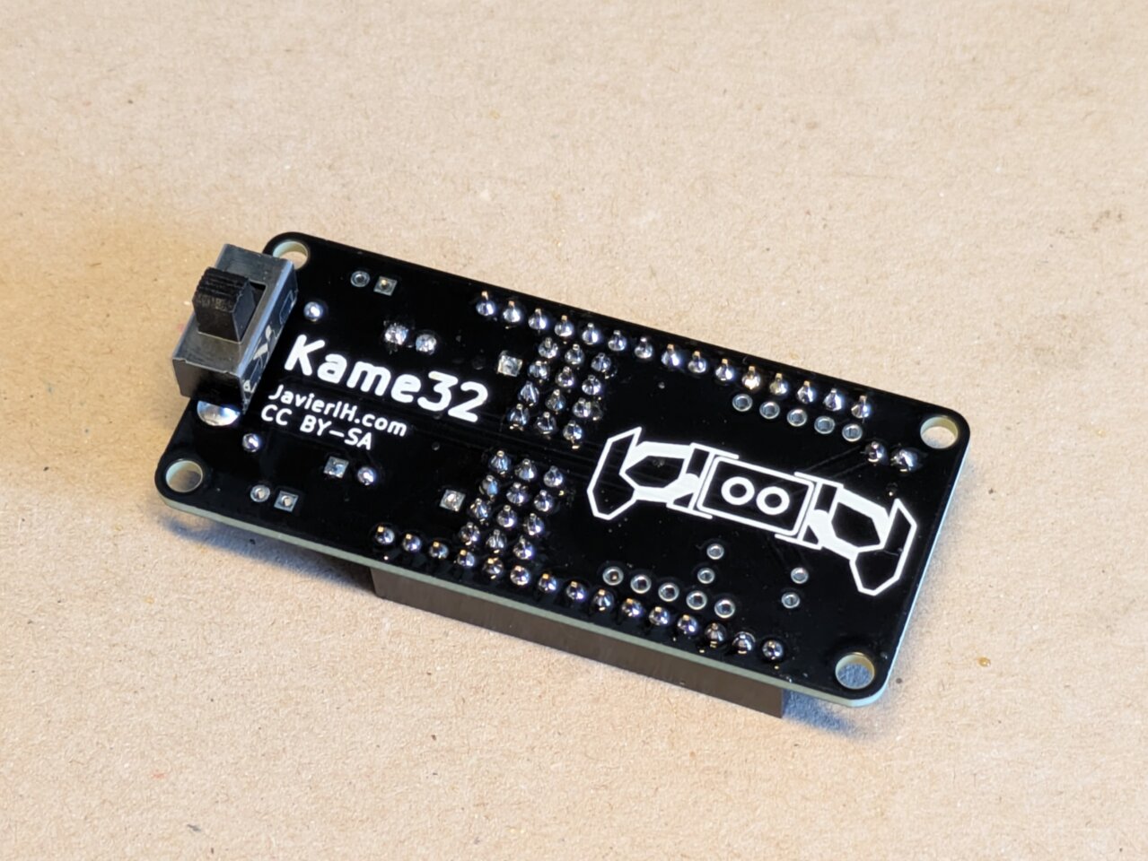 |
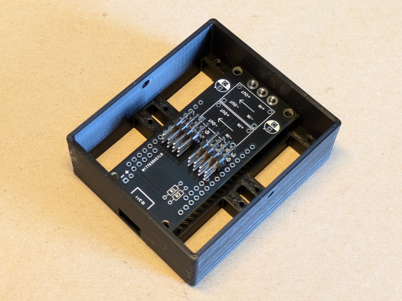
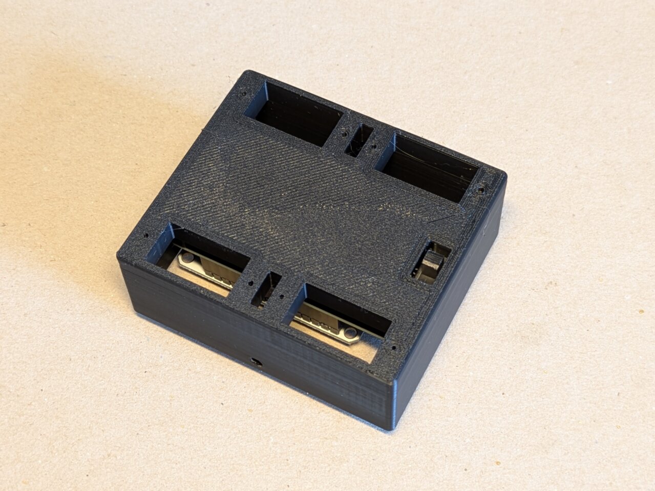
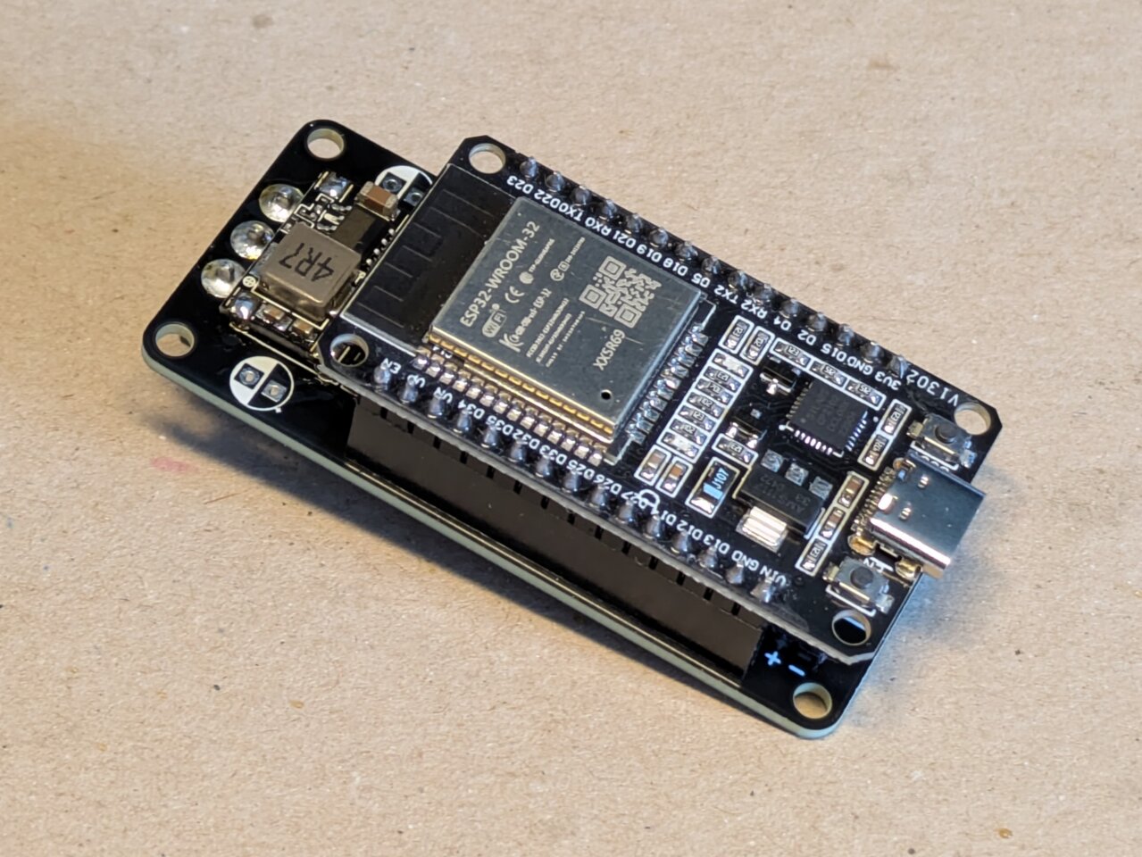
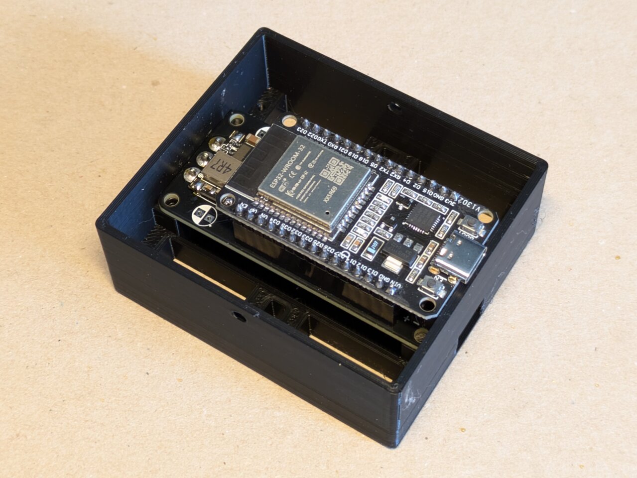
Here’s the fully assembled board, both outside and mounted inside the robot body.
If you have any questions or suggestions, feel free to drop a comment below. Thanks for checking out the guide and for your interest in the project!
Comments